
- #Ip camera pinout wiring diagram how to#
- #Ip camera pinout wiring diagram install#
- #Ip camera pinout wiring diagram manual#
- #Ip camera pinout wiring diagram Pc#
#Ip camera pinout wiring diagram manual#
You can configure the camera setting and IP by the user manual provided by the the manufacturer. Power ON the NVR and check if the live camera recording is showing on monitor as expected. For HD, Use the HDMI cable to connect the Monitor / Laptop with NVR as shown in fig.
#Ip camera pinout wiring diagram Pc#
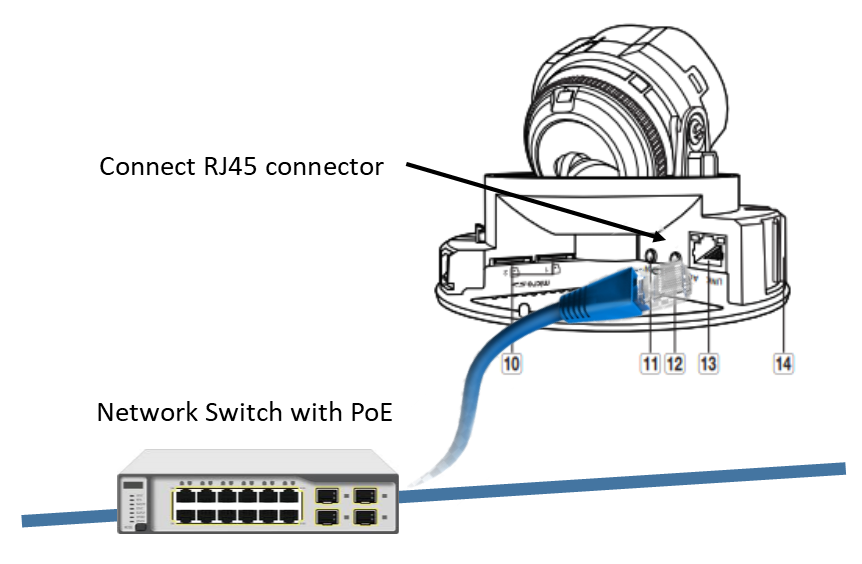
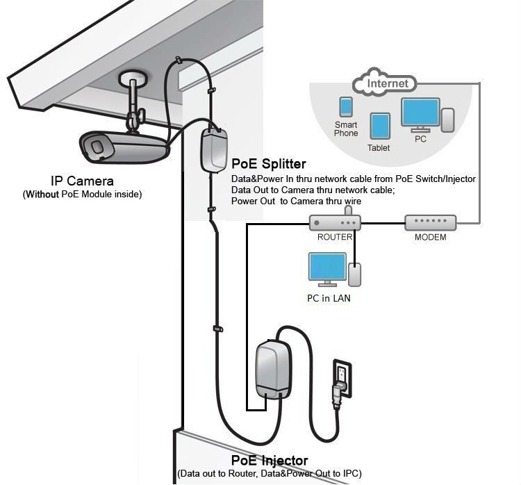
To check if the system works properly, connect the PC / LCD / Monitor by VGA cables.For smooth and reliable operation, it is recommended to connect the camera and NVR to the UPS (Uninterruptible Power Supply System). So you can directly connect the NVR by three pin plug using 120V AC or 230V AC depends on your region. In our case, the power supply is built-in in the NVR system.If cameras are audio enabled, the white RCA cable should be connected to the Input slot in NVR for audio data transmission. Now connect the other end of PoE injector (Cat 5/ Cat 5 or RJ45) to the back side of NVR slots labeled as PoE input ports as shown in fig.This way, the camera is able to transmit the video signal and receive the input power in the same cable. In other cases, up to 35 Watts power can be transmitted over internet and the Ethernet cable length can be 328 feet (100 Meters). You can use passive PoE splitter and PoE Injector and the wire length can be 130 feet (40 meter). As external power doesn’t needed in PoE IP Cameras, therefore connect only the cameras through PoE via Cat5 / Cat 6 cables.Before proper installation, check all the IP cameras locally to make sure they are working properly.Please follow the steps below according to the fig for PoE IP surveillance camera installation. IP Camera Installation Wiring Diagram with NVR System In some NVRs, there is no built-in PoE system and you will have to buy an additional PoE and switch. Also, both PoE ( Power over Internet) and Non-PoE cameras can be connected to the NVR system based on its design. Moreover, NVR is a wire or wireless system where DVR doesn’t support wireless system. Keep in mind that only IP camera ( Internet Protocol) can be used with NVR system as compared to DVR where analog camera are used. in NVR system, the video data encode and process at camera in digital format and send it to the NVR recorder to store it in a hard drive inside the NVR which can be view later by monitor or remotely if it is connected to Ethernet router. As the name suggests, it based on networking as the input signals are from a network as compared to DVR where the input signals based on direct wire connection. Router (To view and control the camera by smartphones through Wi-Fi)īefore we go in details, lets know that what is the NVR and how it works? What is NVR?.Power Supply, adopter, power splitter and other related cables and connectors such as VGA cables, RJ45 etc.PoE IP CCTV Camera (Bullet, Dome or PTZ Cameras).Optional Wiring Connection of DVR Security & CCTV Camera.IP Camera Installation Wiring Diagram with NVR System.

#Ip camera pinout wiring diagram how to#


As the NVR is network base system, it can be wired or wireless system with high range and can be used with multiple channels. Nowadays, NVR comes up with built-in switch hub and power supply and replacing the DVR system. DVR ( Digital Video Recorder) system was the best system for local home user with less amount of Closed Circuit Television ( CCTV) due to its price range as compared to NVR ( Network Video Recorder) system because, they need extra switches and low maintenance. The security systems also improved by designers e.g. In the latest technology era, AI security and surveillance is taking the major role in protection systems of sensitive areas with appropriate information than human being. PoE IP CCTV Camera Installation Wiring with NVR – Step by Step


 0 kommentar(er)
